BRITISH AUTOMOTIVE |
|
www.mgbmga.com MGTD Articles |
Technical Information (MGB 4)
Composite Leaf Springs
Last Modified - 06/24/01
We realize that this lowered rear ride height may not be acceptable to some MGB owners. To that end, we can supply you with the following:
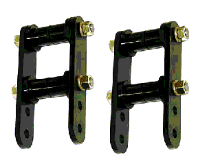
Part # RRHASK: This kit, when fitted in conjunction with OEM STEEL SPRINGS, will allow approximately between 1/2" to 1" increase in your vehicles rear ride height.
Rear Ride Height Adjustable Shackle Pin Kit

If your vehicle is fitted with COMPOSITE SPRINGS, this kit must be fitted in conjunction with part # RRHAFBK/C (chrome bumper vehicles) or part # RRHAFBK/R.(rubber bumpered vehicles) UNDER NO CIRCUMSTANCES SHOULD PART # RRHASK BE FITTED ALONE.
The above illustration shows the kit with 8 polyurethane bushings. Also provided, but not shown, are 8 Delrin bushings.
The kit contents are as follows:
4 - Shackle pins .500" OD
4 - Shackle pin links
8 - 3/8" SAE nuts
8 - 3/8" lockwashers
8 - Delrin bushings
8 - Polyurethane bushings (95 Durometer scale)
1 - 3/8" SAE jam nut
1 - Lube
This rear ride height adjustable shackle kit may be an attractive purchase for those MGB owners who wish to take long trips but can not bear to see the backend of the vehicle dragging on the ground when loaded with luggage, spare parts and tools etc. Relatively simple jobs to change your rear ride height as you desire. OEM STEEL SPRINGS ONLY!
Installation of this kit may effect the way in which your vehicle handles. Remember INCREASING rear ride heights INCREASES the roll center heights and rear wheel UNDERSTEER.
For ease of installation, polyurethane (95 Durometer scale) shackle pin bushings are now provided as well as their Delrin counterparts. These polyurethane bushings require no custom fitting.
1. Refer to your workshop manual for rear spring shackle bushing replacement.
If you intend to install the provided Delrin bushings, they will need to be "custom fitted" with the prudent use of a flat file to prevent "Binding".
Remember the following is a dry run so make sure that the surface and the inside of the rear spring eye is deburred and that the upper shackle bushing body insert tube is free of rust and scale.
2. Place the Delrin bushings into the spring eye, position and insert shackle pin. Fit one of the shackle links and secure with 3/8" SAE nut (no lockwasher). Eyeball the position of the pin within the opposite Delrin bushing, this will give some indication of the amount of material to be removed. Once you are sure after filing that the pin is level with the surface of the Delrin bushings, attach the outer shackle and secure with 3/8" SAE nut. Securely tighten both nuts and check for "Binding". Remove further material as necessary.
3. Carry out the same procedure for the upper shackle bushing assemblies.
The 3/8" jam nut is provided to assist you in loosening the nuts, in all probability only one nut will come loose, we then use this jam nut, along with the regular loose nut, and lock together. This method will then allow you to remove the other nut.
CAUTION: Do not overfile the bushing face otherwise lateral spring movement, within the shackle, will occur.
4. Lubricate the surfaces of the polyurethane and or Delrin bushings, this also includes the pins. Insert pins into the bushings and attach shackle links, secure finger tight with 3/8" nuts and lockwashers.
5. Moderately tighten shackle assemblies.
NOTE: Final tightening of all hardware should be done with the vehicle on the ground.
Vehicle must be supported with axle stands placed under the vehicle body.
1. Slacken U-bolts only.
2. Place jack under center tube and take the axle weight off the springs.
3. Remove existing shackle assemblies, discard OEM rubber bushings. Clean all rust and scale from inside the rear spring eye, also including the upper shackle bushing body insert tube.
4. Continue with previously outlined instructions.
REAR RIDE HEIGHT ADJUSTABLE FRONT SPRING EYE BRACKET KIT
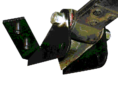
The following image shows the installed chrome bumper adjustable ride height front bracket prior to increasing the ride height. Part # RRHAFBK/C

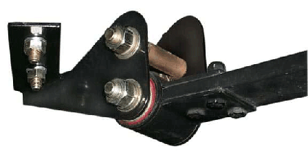
The following image shows the installed chrome bumper adjustable ride height front bracket immediatly following installation. Part # RRHAFBK/C

The above illustrations show the major components that make up this kit. There are 2 different styles of kits available: When fiited in conjuction with PART # RRHASK this kit will further increase your vehicle rear ride height by approximately ¾".
1. All chrome bumpered MGB and MGBGT PART # RRHAFBK/CB PRICE US$ 85.10
2. All rubber bumpered MGB and MGBGT PART # RRHAFBK/RB PRICE US$ 85.10
The kit contents are as follows:
2 - Inner left-hand and right-hand support brackets
2 - Outer left-hand and right-hand support brackets
2 - Spacer tubes
4 - 7/16" SAE bolts
4 - 7/16" SAE nuts
4 - 7/16" lockwashers
8 - 7/16" SAE flat washers
4 - 7/16" SAE spacer washers
4 - 5/16" SAE bolts
4 - 5/16" SAE flat washers
4 - 5/16" lockwashers
2 - 1/4" SAE bolts
2 - 1/4" SAE flat washers
2 - 1/4" Lockwashers
This kit must be fitted in conjunction with the rear ride height adjustable shackle pin kit for the following reason: (COMPOSITE SPRINGS ONLY)
Since the design of the composite spring dictates that the blade cross-sectional area be less than the front section (as measured from the rear axle locating centerline) any attempt to increase the vehicle rear ride height by simply installing the adjustable rear ride height shackle kit will result in excessive loads being placed upon the rear section of the composite spring along with blade de-arching which, could result in premature blade fatigue with ultimate breakage.
These instructions should be read in conjunction with the appropriate section of the MGB workshop manual i.e. rear road spring replacement as well as our instructions for installing the rear ride height adjustable shackle pin kit and composite spring installation instructions.
NOTE: Some instructions may be duplicated within these texts.
When working with the drivers' side (left-hand drive) you will need to remove the rear section of the exhaust system.
NOTE: FOR EASIER INITIAL INSTALLATION USE FLAT WASHERS ONLY. INSTALL THE PROVIDED LOCKWASHERS UPON FINAL ASSEMBLY. ALSO, ALL JAGGED EDGES, CAUSED BY DRILLING, MUST BE FILED FLUSH. WORK ON ONE SIDE AT A TIME. START ON THE RIGHT HAND SIDE FIRST.
1. Using your MGB workshop manual as a guide, remove the front spring mounting bolt, then lower the spring down to clear the road spring support.
2. Locate inner and outer support brackets. Insert upper mounting bolt and tube, finger tighten nut. Align brackets so that they are vertical and also horizontal. Use a small "level" for this purpose. Tighten nut to prevent bracket movement.
3. Mark location of the upper floor panel attachment holes and pilot drill (1/8"). (Be sure to pull back carpets to avoid damage from drill bit). Remove support brackets.
4. From inside the vehicle locate the 3 1/8" pilot holes. Remove sound deadening material then drill the outer hole to 17/64". Drill the remaining 2 pilot holes to 21/64".
5. Reinstall support brackets and upper mounting bolt and tube. Make sure vertical and horizontal alignment is OK then tighten upper mounting bolt assembly followed by the support bracket hardware.
NOTE: If the floor pan is not flush with the support bracket mounting brackets use the appropriate amount of flat washers necessary to rectify this situation.
6. Lube and install front spring eye bolt along with the 2-spacer washers.
NOTE: Final tightening of this item, as well as the rest of the hardware, must be done with the vehicle on the ground.
For additional information select from one of the following categories: