|
|
BRITISH AUTOMOTIVE |
|
www.mgbmga.com MGTD Articles |
Composite Spring Redesign
Last Modified - 5/9/05
British Automotive has redesigned its latest production of MGB135# composite springs. These new spring blades are slightly longer than their predecessors, resulting in an increase of the rear compliant cross sectional area. However, spring rates, ranging from 140# to 155# for this production run, remain virtually unchanged from previous production runs. Total weight, with all mounting hardware, including adjustable rear shackle assembly, approximately 6.75 lbs. per spring blade.
This new composite spring design features a new rear spring mounting eye assembly which is virtually identical to that of the front. See the following image P0002784.
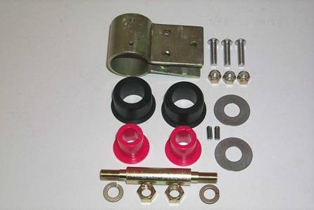
Components for one side are as follows:
Composite Spring Eye (3/16" holes pre-drilled)
1/4" SAE x 1" Stainless Steel Button Head Screws (3)
1/4" SAE Nyloc Nuts (3) Grade 8
Delrin Support Bushings (2)
Polyurethane Insert Bushings (2)
3/16" x 1/2" Stainless Steel Roll Pins (2)
Stainless Steel Thrust Washers (2)
Threaded Shackle Pin .565" OD
3/8" SAE Nuts (2) Grade 8
3/8" Lockwashers (2) Grade 8
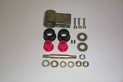
Components for one side are as follows:
Composite Spring Eye (with 3/16" holes pre-drilled)
1/4" SAE X 1" Stainless Steel Button Head Screws (3)
1/4" SAE Nyloc Nuts Grade 8 (3)
Delrin Support Bushings (2)
3/16" X 1/2" Stainless Steel Roll Pins (2)
Stainless Steel Thrust Washers (2)
7/16" SAE Nut Grade 8 (2)
7/16" SAE Jam Nut (1) NOTE: Only one provided. Use on either side.
7/16" Flatwasher Grade 8 (2)
7/16" Lockwasher Grade 8 (2)
.565" OD x 2.125" Support Tube with 7/16" OD Shank with Pin Assembly (7/16" SAE Thread X 4-1/4" Length)
NOTE:
The Delrin support bushings are held within the spring eye by clamping pressure as well as a small amount of epoxy.
The red polyurethane bushings are inserted "dry".
An added precaution, to prevent both the Delrin support bushings and the red polyurethane bushings from rotating within the spring eye, is the inclusion of 3/16" x 1/2" stainless steel roll pins.
For your convenience, we have pre-assembled the front spring eye and the rear spring eye/shackle assemblies with "Super Flex" polyurethane assembly lubricant. Other than when replacing the "red" polyurethane insert bushings, there is no need to dismantle these assemblies.
With this new rear composite spring eye assembly design, it was found necessary to incorporate the fitting of British Automotive's adjustable rear shackle pin kit as an integral part of the composite spring package. See following image P0002787.
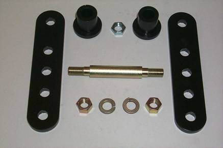
The adjustable shackle side links have been set in the OEM shackle center to center pin position depth. Since, the rear compliant cross sectional area of the composite spring blade has now been significantly increased, the rear suspension ride height can now be increased, in 1/2" increments for a maximum of 1", by relocating the lower shackle pin within the side links. Although the center to center adjustment holes are 1" apart, we only gain a total of 1/2" per hole. This is due to the fact we are only altering one spring mounting position.
NOTE: Please make note of this OEM position.
CAUTION! No provisions have been made for lowering the ride height with this method. Do not move the shackle pin location to any other hole position, other than those that increase ride height.
The composite spring rear axle locating and mounting hardware still remain the same. These components are shown in the following image P0002766.
PLEASE SEE IMPORTANT INFORMATION FURTHER IN THIS TEXT
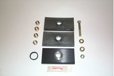
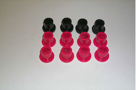
One of the major advantages with this new composite spring kit is the inclusion of replacement front (4) and rear (4) red polyurethane insert bushings. Along with this, we also include (4) new upper black polyurethane shackle pin bushing. This will allow the owner the opportunity to replace the original installed polyurethane bushings when necessary. See following image P0002776.
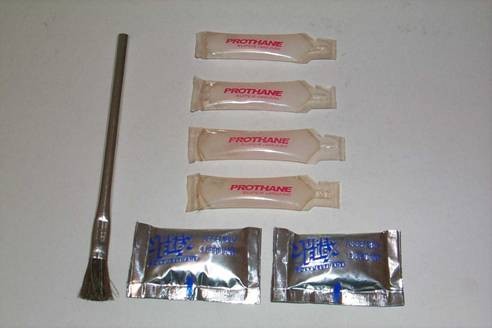
We supply 4 tubes of "Prothane" lubricant with the composite spring set. One tube per side is recommended during the installation of the composite spring nylatron seating pads. Two tubes are left in reserve for future use. See previous image P0002766 and the following image P0002790.
Also supplied are 2 pouches of “Super Flex” polyurethane assembly lubricant. Use one pouch for the fitting of the front spring eye mount, rear spring eye mount and upper shackle black polyurethane bushings. This will leave one pouch to use during the replacement of the front and rear red polyurethane insert bushings, as well the upper shackle pin black polyurethane bushings, when required. See following image P0002790.
The following instructions are meant as supplemental instructions to those found in various MGB service manuals covering road spring removal and refitting. The rear axle should remain supported, as in the removal of the original springs.
IMPORTANT INFORMATION BEFORE INSTALLATION
The inner surfaces of the front spring mount body abutments should be deburred and smooth, likewise, the upper rear shackle pin bush mounting
holes should be clean.
PRELIMINARIES
Please read the following paragraph titled "IMPORTANT INFORMATION" that follows below.
A. Remove the nylatron pads and 1/2" spacers from the composite spring blades.
B. Using the supplied application brush, apply "Prothane" lubricant to the inner surfaces of the nylatron pads.
C. Compress the nylatron pads back on to the composite spring blades.
NOTE: To duplicate the approximate thickness of the OEM steel spring, the nylatron spring seating pad with the black nylon ring attached, along with the 1/2" spacer block, fits to the lower side.
IMPORTANT INFORMATION
It has been brought to our attention that due to the inconsistencies in the manufacture of replacement "U" bolt guide plates (Moss Motors Part 267-570 banjo axle and Part 267-575 tube axle) it is extremely important that the 1/2" spacer blocks be fully seated within the "U" bolt guide plates.
If required, you should press the two components together using a press, or a soft jawed vise before installing the components on the vehicle.
Apply "Super Flex" lubricant to the outer surfaces of the red polyurethane insert bushings, both sides of the stainless steel thrust washers and the mounting bolt.
Making sure that the stainless steel thrust washers are not displaced from the insert tube fit the composite spring to the body mount abutment. Do not overtighten hardware.
- Dismantle rear shackle links from both shackle pins.
- Insert upper shackle pin black polyurethane bushings "dry" into mounting holes.
- Apply "Super Flex" lubricant to inside surface of these bushings and the .500" upper shackle pin, insert the upper shackle pin with a twisting motion.
- Apply "Super Flex" lubricant to each face of the black polyurethane bushings, as well as the outer surfaces of the stainless steel thrust washers.
- Place upper inner stainless steels thrust washer over shackle pin shoulder, attach inner link and hold in position with nut and lockwasher.
- Remove lower shackle pin stainless steel thrust washers from the red polyurethane bushings, apply "Super Flex" lubricant to the inner and outer surfaces then relocate over shackle pin shoulders.
- Raise the composite spring blade and locate lower .565" shackle pin into inner link. Be sure that the lower inner stainless steel shim is not displaced during this operation. Do not overtighten hardware.
- Install upper outer stainless steel thrust washer over upper shackle pin shoulder.
- Fit outer link to both shackle pins. Be sure that both the outer stainless steel thrust washers are not displaced during this operation.
- While observing that the all stainless steel thrust washers remain in position, gradually tighten hardware.
- Install upper "U" bolt guide plate.
- Lower axle down onto guide plate.
- Install bump stop plate and "U" bolts.
- Install 1/2" spacer block and lower "U" bolt guide plate along with lower shock absorber link/telescopic shock absorber mounting plate.
NOTE: Do not overtighten hardware. All hardware should be tightened with the vehicle on the ground, on individual ramps, or on a shop hoist with wheel ramps.
Please note that composite spring assemblies are only sold with the inclusion of British Automotive's traction control kit. (We currently do not sell composite spring sets separately.) The combined weight of the traction control kit and composite spring assemblies is 15 lbs. per side. This combined weight is still considerably less than one individual OEM steel spring alone. Information on our composite springs can be found under the following technical articles: MGB4A, MGB27, and MGB27A.
Under normal circumstances, and when fitted with OEM shock absorbers, the rear axle check straps control the maximum rear axle rebound distance. However, when the vehicle is fitted with telescopic shock absorbers, this condition is controlled by the maximum extended length of that particular shock absorber.
In the past we have worked with the installation of axle check straps along with the installation of telescopic shock absorbers. However, in our investigation of the MGB RV8 model, which incidently, is fitted with Koni gas charged telescopic shock absorbers as original equipment, we discovered that there were no provisions made for the fitment of axle check straps whatsoever. To that end, we have adopted the same approach and decided to work with the telescopic shock absorber extended length as the primary rear axle rebound control. With this method of control, correct shock absorber installation now becomes of primary importance.
| DIMENSIONS | MGBRV8 (Koni) | MGB (Koni) |
| Extended Length | 17.5" | 16.5" |
| Closed Length | 11.625" | 10.5" |
| Extended Length | 5.875" | 6.0" |
The increase in shock absorber extended length on the RV8 shock absorber is primarily due to the deeper lower mounting bracket depth. This bracket serves as the lower shock absorber mounting point as well as the traction control arm mounting location. This dual purpose mounting location is approximately 1” deeper than British Automotive’s mounting bracket. This dual mounting location also results in the shock absorber working at an increased angle.
The Koni shock absorber, as fitted to the RV8, contains no internal bump stop provision. Therefore, bump stop control, via the OEM method, is retained. This also applies to any other telescopic shock absorber that you may be fitting where there is no such provision.Even if the shock absorber has these provisions, I highly recommend retaining the OEM bump stop set up. This becomes even more important when fitting British Automotive,s new multi position upper mounting bracket which, produces a more positive working angle.
With the assumption that you are converting to telescopic shock absorbers along with the composite spring installation, we need to direct you on the recommended installation procedures.
We recommend installing the composite springs and the traction control arm front brackets, without the traction control bar. Install shock absorbers as outlined in technical article MGB13B. The traction control arm bar can be fitted immediately following this operation.