|
|
BRITISH AUTOMOTIVE |
|
www.mgbmga.com MGTD Articles |
MGB Chrome Bumper Traction Control Arm (TCA) Kit
for Tube Axles with OEM Steel Leaf Springs
Last Updated 11/22/06
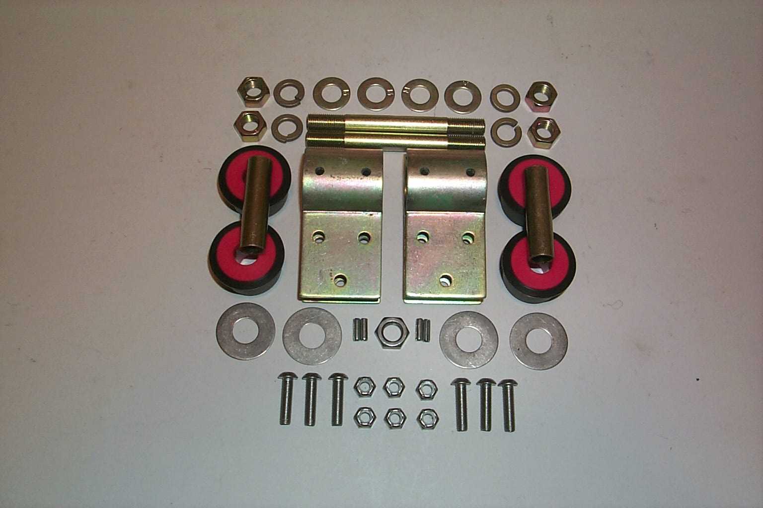
British Automotive has put together a limited number of these kits for the MGB owner. As part of British AutomotiveÆs ongoing retirement plans, we are offering this kit at below actual incurred costs. PRICED @ US$ 300.00.
This kit is suitable for moderate HP output engines. High HP output engines and V8 powered engine units may require additional front TCA mount strengthening modifications. Information on this can be found later in this article.
P0003364
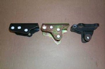
LEFT HAND IMAGE: This is the original rear TCA axle mounting bracket that has been used in the past on MGB tube axle vehicles fitted with our composite springs. Since the composite spring blade depth is less than that of the OEM steel spring assembly, there was no need to have additional depth built into the bracket to accommodate composite spring to TCA bar interference issues under rear axle rebound conditions.
Distance from upper mounting platform to TCA bar mounting hole center 1-1/2ö.
CENTER IMAGE: This is our newly designed rear TCA axle mounting bracket which, can be used with both composite and OEM steel leaf springs. The lower TCA rear-mounting eye has been offset downward 1-3/8ö to allow for adequate clearance as indicated in the previous paragraph.
You will notice that this bracket is etched to simulate the original bracket. Since, we are now using this bracket for both the composite springs and the OEM steel leaf springs, the customer can have these brackets laser cut, or similar process, to eliminate any ground clearance issue that may exist. Obviously, this must be determined before installation.
Distance from upper mounting platform to lower TCA tube mounting hole center 2-7/8ö.
RIGHT HAND IMAGE: This is the actual TCA axle mounting bracket as used on the MG RV8 (PART # ZXC5714).
Notice that the lower telescopic shock absorber mounting point uses the same location as that of the TCA tube. The forward hole is for mounting the anti-roll bar link assembly.
Distance from upper mounting platform to TCA bar mounting hole center 2-7/8ö
 |
 |
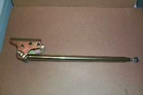 |
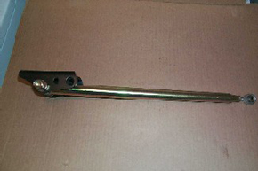
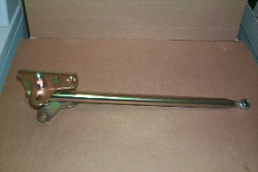
P0003368 | P0003365 | P0003367 |
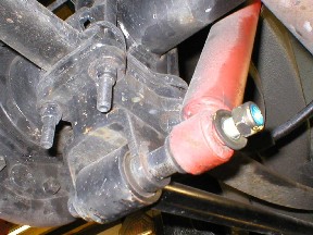
The above images show the TCA tube fitted in the actual rear mounting location.
(VIEWED FROM THE REAR)
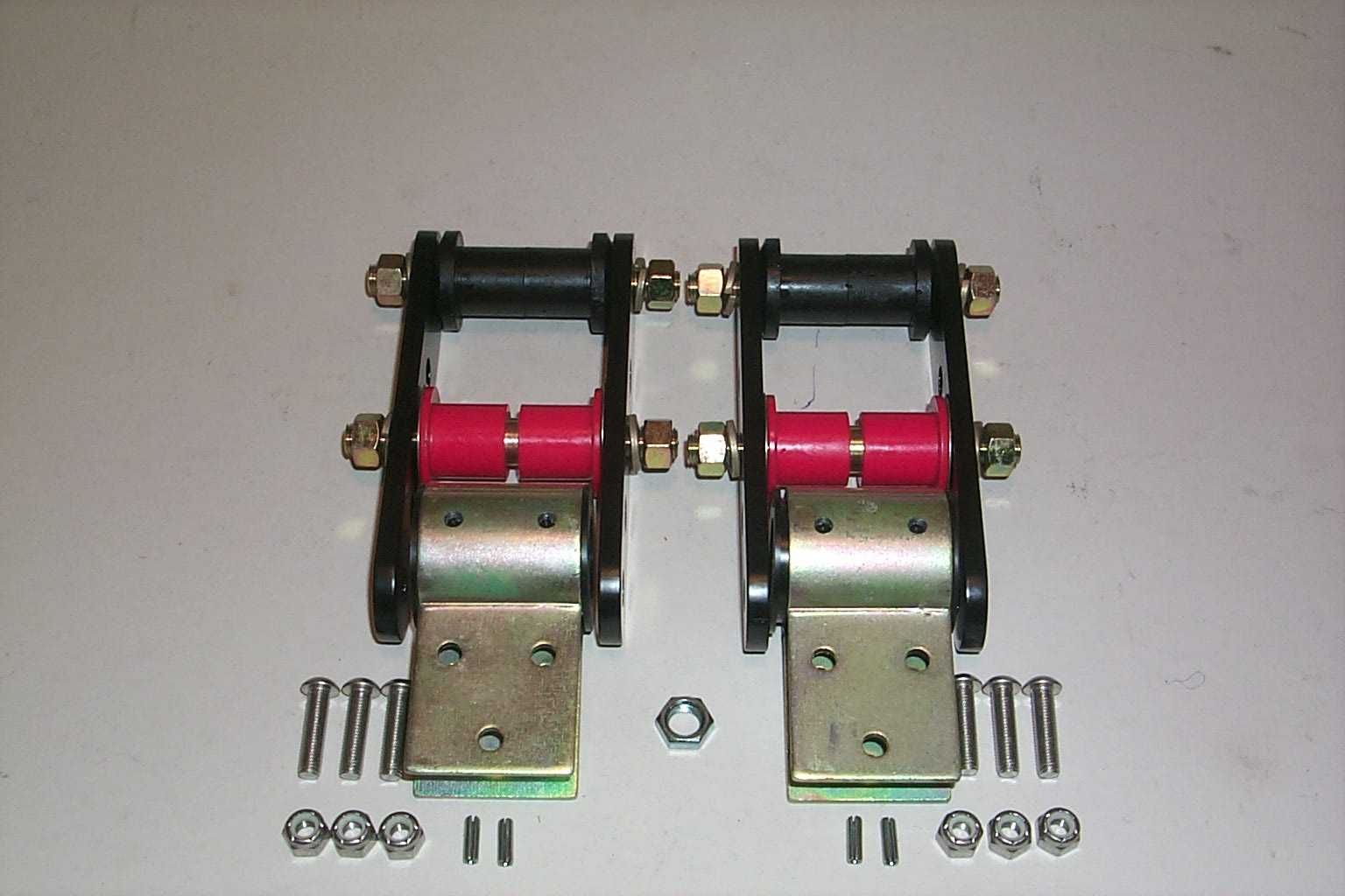
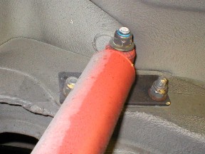
The above image shows the front TCA bar mounting brackets fitted with the OEM steel spring adapter kit. These are the original TCA brackets as fitted to the MGB chrome bumper vehicles (banjo and tube axles) with composite springs, and have a vertical displacement of 1-1/2ö. However, with the installation of the OEM steel spring adapter kit, this measurement is increased to 2-3/4ö.
Please read the following instructions in conjunction with the appropriate section of your workshop manual.
NOTE: Be sure to use oil on all threads and that the nuts are free running.
- Raise the vehicle and support the body just forward of the rear road spring front mounting abutments.
- Remove road wheels
- Support center of rear axle.
- Disconnect center and rear exhaust mounts. Suspend exhaust with bung cords, or like.
- Disconnect axle check straps from their rear axle mounting pins.
- Disconnect the lower OEM shock absorber links, or lower telescopic mounting
- Lower the rear axle sufficiently, not totally.
- Remove the axle ōUö bolts.
- 9. Remove the lower mounting plates.
- Raise the rear axle and install the pre-lubed upper nylatron spring seating pads.
- Lower the rear axle down and install the pre-lubed lower nylatron spring seating pads.
- 12. Install new TCA lower mounting plates.
- With rear axle still supported, undo and remove one front spring mounting bolt. Lube with ōSuperFlexö lube and install new 7/16ö threaded pin.
- Continue with the opposite side.
- Place the black powder coated TCA brackets over the threaded pin, finger secure 7/16ö hardware.
- From underneath mark the location of mounting holes onto the floorpan.
- Remove brackets.
- Pilot drill (1/8ö) these locations on both left hand and right hand side of vehicle.
- From inside the vehicle, locate these pilot holes and drill to 21/64ö (2) and 17/64ö (1) on both driverÆs and passengerÆs side.
- From the underneath of vehicle, deburr these holes.
- Refit brackets and finger tighten secure 7/16ö hardware.
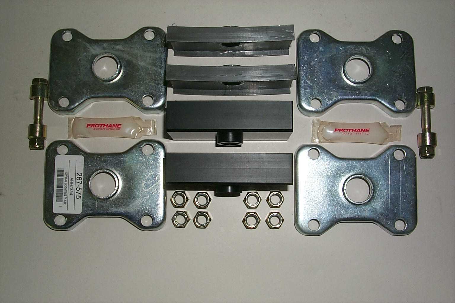
- Install and finger tighten the complete interior mounting bracket hardware. Be sure to install the correct amount of ╝ö flat spacer washers between the outer TCA mounting brackets and the floorpan. We have provided more than an adequate amount of these washers.
- Remove 7/16ö threaded pin hardware along with the 7/16ö SAE x 3.3/4ö bolt and 5/8öOD x 2.560ö spacer tube.
- Install zinc yellow adapter plates over the black powder coated TCA mounting brackets, secure with complete hardware as observed before beginning TCA kit installation.
- With all lockwashers and flat washers in position, tighten all hardware.
- Reverse steps 6 through 1.
- Tighten the ōUö bolt 3/8ö SAE nyloc nuts to 10.0 ft/lb.
- SuperFlex lube the rear TCA tube mounting bushings inner diameter, abutment end faces and the aluminum spacer tube. Insert tube into bushings.
- Assemble TCA tube to the TCA rear-mounting bracket.
- Adjust TCA front heim joint and install hardware.
- Tighten all hardware.
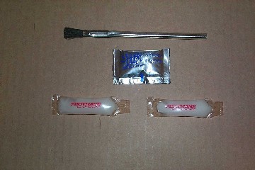
At this stage we recommend the installation of nylatron spring seating pads. These are available under Moss Motors part number 267-555, and must be ordered separately.
NOTE: These nylatron spring seating pads must be lube with ōProthaneö and pressed fully into position.
NOTE: Do not overtighten the 3/8ö SAE nyloc nuts, these will be tightened later to 10.0 lb/ft.
NOTE: Please read the following before continuing.
Remove any interior sound deadening material that will interfere with the flush floorpan contact of the interior mounting hardware.
It is also essential that the underside of the TCA mounting flange brackets have metal to metal contact with the floor pan. Clean any material from the body in these areas. A light coat of black paint will prevent rusting.
NOTE: Depending upon your physical size, it may be easier to remove both passengers and driverÆs seats.
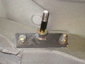
For accurate TCA front mounting bracket to floorpan hole alignment, we recommend the temporary installation of the 7/16ö SAE x 3.3/4ö bolt and 5/8öOD x 2.560ö spacer tube. Accurate marking and drilling of these holes is essential. Having said that, I recommend having an appropriate sized round file on hand.
NOTE: The next set of instructions requires that the vehicle is over an open pit, vehicle ramps, on the ground, or preferably, a ramp style vehicle lift.
For MGB vehicles that are fitted with high HP engine output units, such as V8 power units, the following should be of interest.
| OEM MG RV8 | (CLIVE WHEATLEY MGV8 TCA FRONT MOUNT KIT) | (CLIVE WHEATLEY MGV8 TCA FRONT MOUNT KIT - CONT'D.) |
 |
 |
 |
P0002647 | P0002649 | P0002651 |
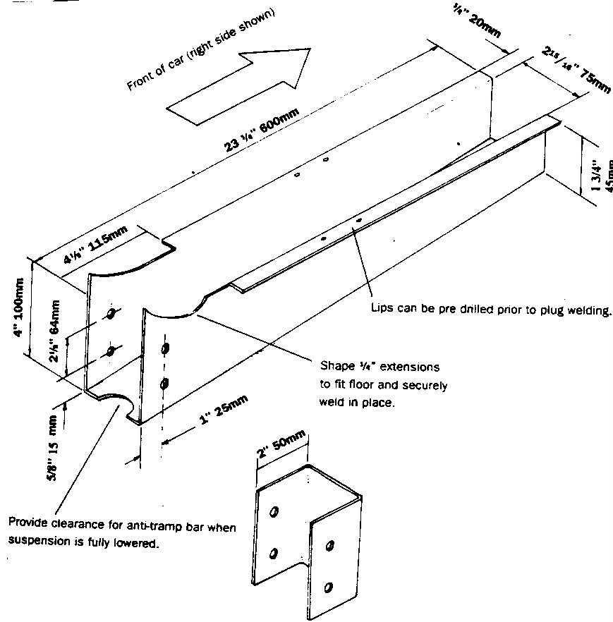
Image P0002647 shows the strengthened front TCA and road spring front mounting abutment as applicable to the factory MG RV8
Prior to carrying out the following instructions, we advise having the complete cooling system, including the heater system, flushed. For environmental reasons, we recommend an approved facility for this operation.
Images P0002649 and P0002651 show Clive WheatleyÆs strengthener kit, which uses stronger gauge steel. Contact Clive or Steve at 44 (0) 1746 710 810 (phone) or 44 (0) 1746 710 999 (fax). You can visit their website at www.mgv8parts.com.
Image TCAKIT.jpg is illustrated in publication ōHow to improve MGB, MGC & MGB V8ö. The Moss Motors part number for this publication is 213-170.
If you are using OEM shock absorbers, you will still use the forward shock absorber link mounting hole as shown in image P0003364 (above).
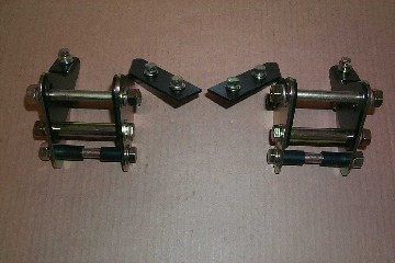
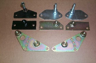
If your MGB is modified with telescopic shock absorbers, your upper shock absorber mounting bracket, in all probability, will look like one of the mounting bracket sets as shown in P0003372 (below).
Top row left hand. British AutomotiveÆs mounting bracket with simple mounting pin. (Can be mounted to either side).
Top row center & right hand. These are left handed and right handed brackets, and are fitted as such. Found in numerous conversion kits.
Middle row left hand. Another mounting bracket with threaded boss instead of mounting pin. (Can be mounted to either side). Also, found in numerous conversion kits.
Middle row center and right hand. A variant mounting bracket set, similar to the set previously mentioned, but with threaded boss instead of threaded pin. Again, found in numerous conversion kits.
When using any of the above upper mounting brackets, the lower shock absorber mounting hole will be the same as indicated for the OEM shock absorber link.
British AutomotiveÆs adjustable upper mounting bracket kit allows for the use of either shock absorber upper mounting points, while using the same lower mounting hole as indicated previously. However, depending upon which of the 4 adjustable mounting holes is used, clearance isssues between the axle tubing and shock absorber body may need to be addressed. More information can be found within technical articles MGB4B and MGB13C.
The OEM MG RV8 upper shock absorber mounting bracket is shown to the right of image P0003372. As you can see the bracket uses the central mounting pin as in British AutomotiveÆs design.
 |
 |
P0003372 | MG RV8 SHOCK BRACKET |
In the images below, we show the actual OEM MG RV8 upper and lower shock absorber mounting assemblies. Installation is left hand side. The Koni shock absorber shown in the image is the uprated version which, can be supplied directly from Clive Wheatley at www.mgv8parts.com.
 |
 |
MG RV8 BOTTOM SHOCK MOUNT | MG RV8 UPPER SHOCK MOUNT |
As you can see the bottom shock absorber uses the same location as the TCA bar rear mounting eye. However, the Koni shock absorber that is fitted to this set up is longer than those supplied with the regular MGB telescopic shock absorber conversion kits.
All upper shock absorber mounting brackets shown in P0003372 can be used with this set up. However, with British AutomotiveÆs adjustable upper mounting bracket the lower mounting boss must be used.
If you decide that you would like to duplicate this OEM installation, British Automotive can supply you with a 1/2ö SAE x 6-1/2ö through bolt for inserting through the rear TCA mounting eye for mounting the lower shock absorber eye.