BRITISH AUTOMOTIVE |
|
www.mgbmga.com MGTD Articles |
Technical Information (MGB 2)
MGB and MGA Clutch Throw Out Bearing
Problems
Last Modified - 3/16/01
I have been meaning to update this article for a very long
time. Many technical articles, including this MGB2 article, were drafted and
filed away as future technical articles. The last modified date that appears at
the upper left hand corner of the first page may, or may not, be the actual
first date that the article appeared on the website. With MGB2 the time between
the drafted article and the website posted technical article was many years.
The development of our STOP/KIT was based upon actual visual
physical damage that we saw on both types of ball/race type throw out
bearings.
1. A black plastic housing type (this style of throw out
bearing is no longer being marketed).
2. A steel housing type
The questions that have arisen concern the above mentioned
2. The one we removed from an MGB had "run dry". Since my paperwork on this has
long vanished, I have no way of identifying the manufacturer of the throw-out
bearing or the year we removed the throw out bearing from the vehicle. However,
we know for sure that the bearing design was prior to the introduction of the
AP(Borg & Beck)style. I also have it in my head that we did the removal
sometime in the mid eighties. Because of this event, we questioned the
longevity of this style of throw out bearing.
In 1992 we installed an AP style throw out bearing into a
British Automotive built 1957 "CARRERA" MGA (see MGA1
Technical Article) for the 1992 "CARRERA PANAMERICANA". No STOP/KIT was
fitted at that time due to the fact that the production of these units was
behind schedule and was not ready prior to transporting the MGA to
TUXLA/GUTIERREZ. We later found out, due to frame modifications we had made
earlier, that the STOP/KIT would not fit anyway. Anyway, just to be on the safe
side, we did take a spare OEM style throw out bearing be with us.
Yes, the AP style is still fitted in the car and is working
as the manufacturer intended. Since the grueling 1992 "CARRERA PANAMERICANA"
(over 2000 miles) the vehicle has had a weekend of SCCA driving at Thunderhill
CA. 2 California Mille events... 2 Monterey Historic trips (not racing)... and
recently in the Summer of 99 I drove it to Reno and back (approx 400
miles).
So, given the environment that the MGA has been driven in, I
think the AP ball/race throw out bearing has more than proved itself and has
survive without the installation of the STOP/KIT.
The next question "Would this type of throw bearing survive,
without the installation of the STOP/KIT, on a MGB or MGA that is driven daily
in say San Francisco or any other hilly area of the USA" ? I really don't know.
All I can relate to MGA and MGB owners is that the original idea behind
designing the STOP/KIT was based upon visual evidence of bearing failure and
both these MGBs were daily drivers here in Marin County.
I have fitted quite a number of the AP throw out bearings as
well as the OEM type and I always install the STOP/KIT on the AP style and give
the customer the option of fitting this kit to the OEM style.
The feed back we have received from the MGB/MGA owners who
fitted this kit have been positive, the only problems encountered have been
hydraulic. The clutch M/Cyl seals must be in good condition, any weakness in
this area will be exposed with the fitting of the STOP/KIT.
Question... Should you the MGB owner install an AP style
ball/race type throw out bearing without the installation of the STOP/KIT?
Answer... Whenever you install the OEM or an AP throw out
bearing you can prolong the longevity of either style by the installation of
the STOP/KIT.
The OEM designed slave cylinder (hydrostatic) eliminates the
need for clearance between the throw out bearing face and the clutch cover
thrust pad; these two parts are always in contact with each other. This system
was also self-compensating for clutch disc wear. The OEM throw out bearing
survived reasonably well under these conditions.
Other vehicle manufacturers use similar hydraulic clutch
systems, but, I have never seen a system that employs a clutch slave cylinder
the size of the MGB (bore size 1.25". This results in a high residual line
pressure and is further compounded by the throw out bearing arm leverage ratio.
This residual hydraulic pressure acts directly upon the throw out bearing face
and the clutch cover thrust pad. Any increase in this residual pressure such
as: the driver inadvertently using the clutch pedal as a foot stop will only
compound the wear rate of both the OEM and AP throw out bearings.
OPERATION
When the clutch pedal is depressed the slave cylinder and
clutch release fork move against and overcome clutch cover diaphragm/spring
pressure. Upon releasing the clutch pedal the clutch cover thrust pad forces
the pushrod back into the slave cylinder to a point where the return spring
will continue to pull the clutch release fork back against the adjustable stop
plate abutment. Without this stop plate the return spring would simply continue
to pull the pushrod back into the slave cylinder, this would result in the
evacuation of hydraulic fluid back into the clutch master cylinder reservoir.
If this was allowed to happen, the clutch pedal would have to be repeatedly
"pump up" to regain hydraulic line pressure. Static clearance between the
clutch fork arm and the stop plate abutment should be set at 1/16".
INSTALLATION INSTRUCTIONS
1. Remove pushrod and slave cylinder from the
transmission.
2. Install the correct new pushrod (68deg MGB 55deg
MGA).
Note: Due to clearance problems with the tubular
cross brace, the MGB pushrod will not fit the MGA.
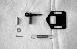
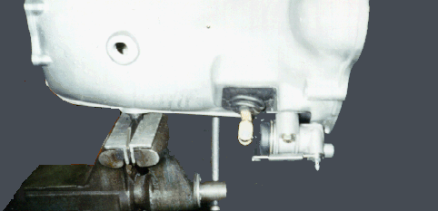
3. Position large slotted bracket between the slave cylinder
and the transmission, tapered abutment-facing rearwards. Install bolts and
finger tighten only.
4. With the throw out bearing contacting the clutch cover
thrust pad, adjust slotted bracket so as to give 1/16" clearance between the
slotted bracket and the clutch release fork. Tighten slave cylinder bolts and
recheck for proper clearance.
5. Hook the clutch return spring thru the small hole in the
pushrod, then loop it around the bleeder fitting.
6. Double check for correct clearance.
Note: Periodic checking and adjusting of the clutch
clearance will be necessary, especially after renewing the clutch disc.
MGB CLUTCH MECHANICALS
For fast road use, autocross or rallying, consider updating
the clutch cover and clutch disc as follows:
Clutch Cover
Use Borg & Beck unit P/N 190-810.This unit provides more
clamping load with only a slight increase in pedal effort. OR use Borg
& Beck unit P/N 190-080 and Modify*
Clutch Disc
Use Borg & Beck unit P/N 190-820 and Modify*
*We highly recommend contacting Midway Industries
Inc. (Centerforce) 520 771 8422. If you send them your new clutch Cover P/N
190-080 they will test, record and modify the existing pressure loads. They
also supply a dual friction clutch disc, which I must say is a very interesting
concept. They will send you brochure upon request.

Stop Kit

Clutch Hydraulic Clearance - Stop Kit Location