|
|
BRITISH AUTOMOTIVE |
|
www.mgbmga.com MGTD Articles |
Technical Information (MGB 16B)
Harland Sharp Roller Rockers Update
Last Updated 2/28/07
We would like to bring to your attention the fact that British Automotive’s Harland Sharp MGA & MGB roller rockers are custom manufactured by Custom Speed Parts, and that these roller rockers, although looking identical, are different than those being offered by the same manufacturer to other purchasers.
Using the following image as reference, we would like to clarify these differences.
- We use a .541” OD roller as opposed to the original 0.607”.
Why? To promote better rocker arm geometry. - The pushrod cup bore area is enlarged.
Why? So as to prevent any possible pushrod cup to rocker body interference. - There is no radial oil groove machined inside the roller rocker bushing bore.
Why? We use a different method of lubrication. - We do not use the oilite bushing that is supplied as stock.
Why? We have experienced high bushing wear rates with this type of bush. - What type of bushing do you use?
We use the OEM factory bushing as used on the OEM rocker arms. - Why do you use this type of bushing?
We have found that this type of bushing has a longer life, and is preferable even over the needle roller type. - What methods are used to install the OEM factory bushing?
- The roller rocker extrusion is bored to the same ID as the original OEM factory rocker shaft bore.
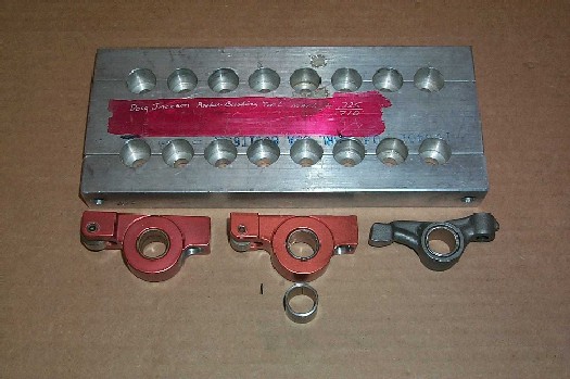
- The OEM factory bushing width is machined to between 0.715” to 0.725” (see jig in image P0003456). This particular width ensures that the bushing can be centralized within the roller rocker extrusion (0.750” width).
- The bushing is pressed into the bore in exactly the same position as the OEM rocker arm. The factory indicates that the bushing split should be at the top, which leaves the oil trough at the bottom, thus providing an oil film under operating conditions.
- 3/32” oil transfer holes (2) are drilled to provide lubrication for the pushrod
cup and roller tip to valve stem end, this is identical to the OEM rocker arm
lubrication.
NOTE: This operation is carried out before the installation of the roller tip. - On one side of the bushing a hole is drilled to accept a 1.6mm OD x 6mm solid pin. Installing this pin ensures that the bushing is prevented from turning for any reason. (See middle roller rocker assembly in image P0003456).
- The bushing is then honed to specifications for fitting with a hardened rocker shaft, be it tuftrided, or nitrided.