|
|
BRITISH AUTOMOTIVE |
|
www.mgbmga.com MGTD Articles |
Technical Information (MGB 15)
Panhard Rod
Last Modified - 11/07/02
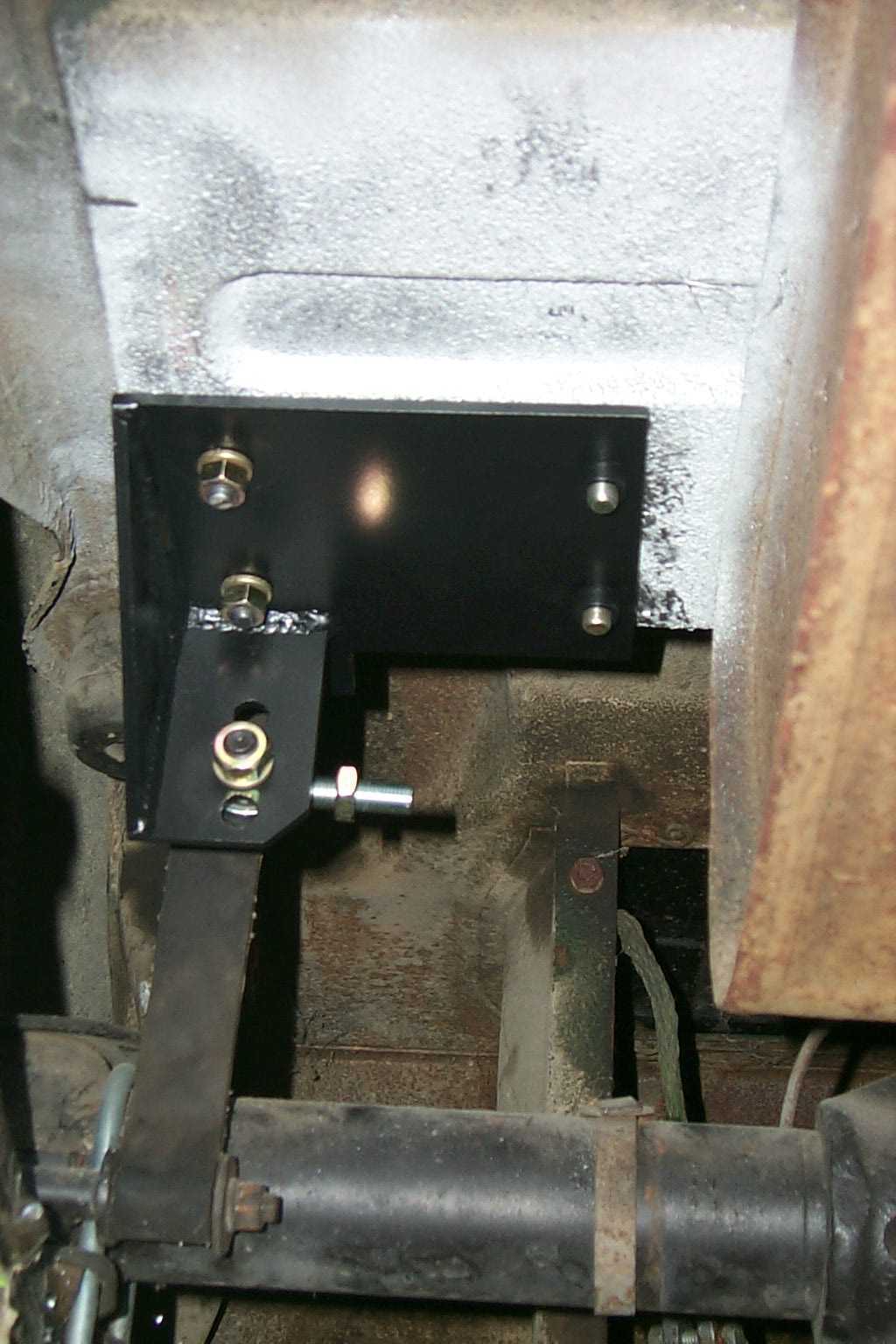
On the left is our new and improved Panhard abutment bracket and on the right is its predecessor. You will note that it has been substantially redesigned to provide greater rigidity.
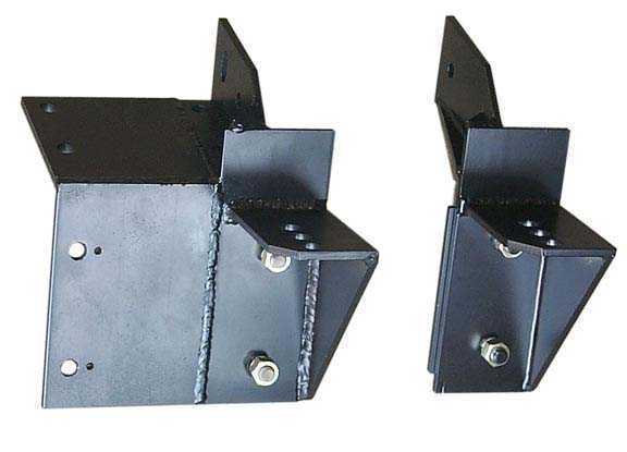
PANHARD ROD ABUTMENT BRACKET
KIT INFORMATION
The fitting of this part is, without doubt, one of the major handling improvements that you can make to your MGB. Recommended for use with either OEM steel or composite rear road springs, whose benefits are listed below:
- Reduced lateral body movement over the rear axle.
- The ability to align the rear axle for reduced thrust angle.
- Both of the above items result in reduced rear axle bump steer.
- Elimination of rear axle "torque steer"
- In many cases the rear inner fender to tire clearance problems are resolved, allowing the use of 15" road wheels and modern 195 X 60 X 15 low profile performance tires.
Originally, our first concerns were with worn steel type leaf springs and the fact that the problems listed below would reoccur again after installing OEM steel springs, albeit over a period of time.
- Leaf springs sag.
- Rear axle torque steer.
- Tire to inner fender clearance problems.
We set about designing and fabricating an adjustable and “bolt in” type panhard rod, which would also be easy to install. When the finalized version was fitted, a full four-wheel alignment was carried out, and as you can see from these alignment readings, improvements were made to the rear suspension geometry. With zero rear axle thrust angle and equal left and right rear wheel toe, a noticeable improvement in handling characteristics was experienced, all thanks to the adjustable panhard rod bar. Fitting 15" wheel rims shod with MICHELIN MXV195-60-15 tires made further improvements in road handling. Below are the before and after rear wheel alignment readings:
Before: |
|
Left |
Right |
|
|
Camber |
+0.01 |
-0.01 Deg. |
|
|
Toe |
-0.08 |
+0.01 Inch |
|
|
Total Toe |
-0.07 Inch |
|
|
|
Thrust Angle |
-0.09 Deg. |
|
|
After: |
|
Left |
Right |
|
|
Camber |
+0.01 |
-0.01 Deg. |
|
|
Toe |
-0.03 |
-0.03 Inch |
|
|
Total Toe |
-0.06 Inch |
|
|
|
Thrust Angle |
0.00 Deg. |
|
|
The aluminum axle-clamping bracket clamps to the R/H rear axle tubing. The L/H abutment bracket fits snugly to the L/H area of the truck floor well and rear axle check strap. Both the aluminum axle-clamping bracket and the L/H abutment bracket have 3 vertical holes for panhard rod horizontal alignment. In addition, the aluminum-clamping block can be rotated. Adjustment of the panhard rod is by way of L/H and R/H heim jointed rod ends.
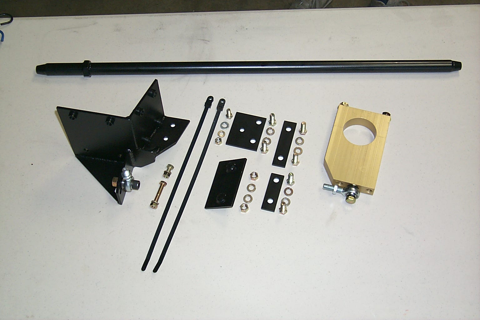
PANHARD ROD KIT (OEM DISC WHEELS)
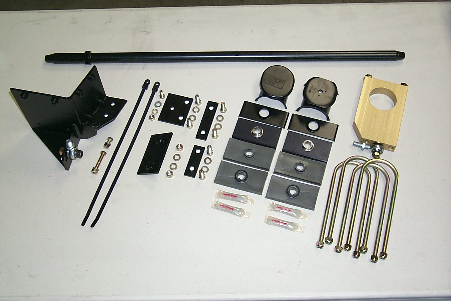
PANHARD ROD KIT (OEM WIRE WHEELS)
NOTE: Before starting the installation of the panhard rod be sure that the underside area, where the L/H abutment bracket is to be installed, is smooth enough for good surface to surface contact.
Deburr all drilled holes.
Depending upon the accuracy of the holes that you are about to drill, it may be necessary to have a 3/8" round file on hand.
PANHARD ROD INSTALLATION INSTRUCTIONS (GENERAL)
1. Jack up vehicle and support with axle stands placed under the rear axle tube assembly.
2. Remove left road wheel.
3. Remove left rear axle check strap from the upper mounting.
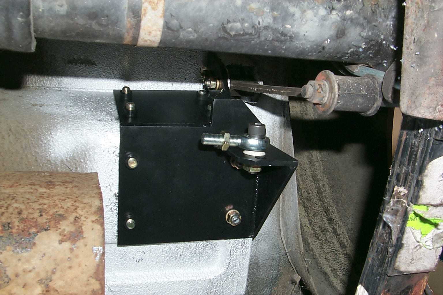
4. Accurately positioned the L/H abutment bracket assembly against the underside of the trunk well (see images below for position). Scribe the two lower bracket hole peripheries. Remove bracket and drill pilot holes 1/8" followed by 25/64”.
5. Position strengthener plate "A" through trunk floor. Place bracket into position and fit 3/8” nuts (without lockwashers). Tighten hardware.
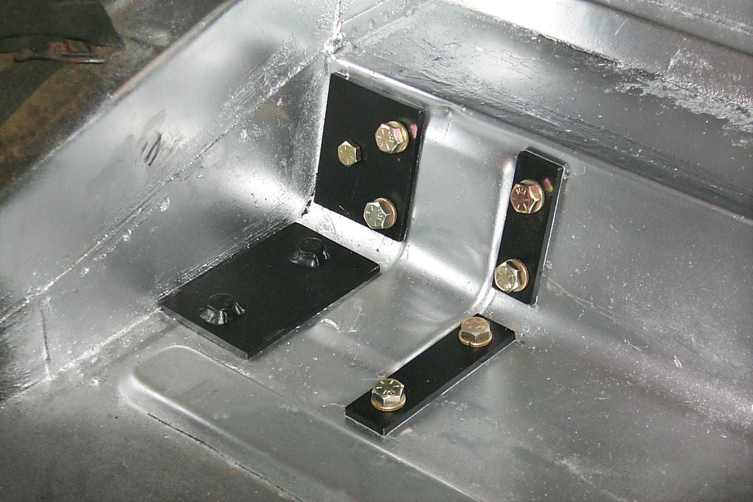
6. Scribe all remaining pem nut hole peripheries through bracket onto the underside of trunk well.
7. Remove bracket. Drill out scribed hole peripheries as mentioned in #4 above.
8. Place bracket back into position. Install 3/8" nuts with lockwashers. Finger tighten hardware.
9. From inside trunk, install strengthener plates "B", "C", and "D" and tighten hardware.
10. Remove 3/8" nuts, as referred to in #8. Install 3/8" lockwashers and nuts. Tighten hardware.
11. Drill (21/64") through the remaining hole on the strengthener plate "D". Install 5/16" X 3/4" SAE bolt, flat washer, lockwasher, and nut. Tighten hardware.
12. Using same drill as above, drill through the hole located on the upper portion of the bracket. Install the 5/16" X 3/4" SAE bolt, lockwasher and nut. Tighten hardware.
13. Using the same size drill, drill through the original upper axle check strap-mounting hole, into and through the bracket.
NOTE: If you are installing a wire wheel panhard rod kit, jump to the section below titled “WIRE WHEEL TUBE AXLE” and continue with the installation.
14. Re-install check strap using 5/16” x 2” bolt, lockwasher & nut. Tighten hardware.
13A. Refit and tighten road wheel.
14. Install R/H aluminum axle clamping bracket, with letters opposite each other (be sure to clean off excess welding bead on the axle tube to ensure effective clamping), tighten clamping bracket sufficiently so as to allow rotational movement.
15. On 1970-1974 models, to prevent panhard rod to gas tank metal pipe contact, it is recommended that a section of the pipe be cut out and substituted with a section of 1/4" fuel hose and hose clamps.16. On 1968-1976 models, remove the handbrake compensator assembly and completely dismantle. Place mounting bracket in a suitable vise and, using 10" or 12" adjustable wrench, bend to the angle shown in Diagram B. Reassemble handbrake compensator assembly.
NOTE: Do not attempt to bend bracket without first completely dismantling. Trying to bend the mounting bracket by using the pin as a lever will only result in a bent pin.
17. Install panhard rod ends equally. (Be sure to lubricate rod end threads). Position rod assembly in the centers of both the L/H abutment bracket and the aluminum axle-clamp bracket. Make sure that the panhard rod is fitted with the large holding nut on the left-hand side.
NOTE: Upon final assembly the handbrake compensator must lie on the inside plane of the panhard rod.
18. To prevent the probability of the inner handbrake cable hanging up on the L/H abutment bracket (1968-1976 models only), join the two tie wraps together around the handbrake inner cable and axle tube.
19. Apply grease to the area where the handbrake outer cable contacts the differential.
20. The next operation must be carried out with the vehicle on level ground or on an appropriate hoist. The panhard rod horizontal position can be achieved by rotating the aluminum axle clamp. Using a small level, rotate the clamping bracket until the panhard rod is level. Make sure that the brake drum handbrake lever will clear the aluminum axle clamp. Use lower adjustment holes on the L/H abutment bracket and aluminum axle-clamp bracket if interference exists. Tighten aluminum axle-clamp bracket bolts to 40ft/lb.
NOTE: Both the aluminum axle-clamp bracket and the L/H abutment bracket have 3 vertical adjustment holes to establish the horizontal position of the panhard rod. The position that you choose depends mainly upon your vehicle ride height. In cases where the vehicle ride height is extremely low it may be necessary to relieve the area of panhard rod to body contact with the prudent use of a large hammer. Road test vehicle for any contact problems. When you are satisfied that you have taken care of contact problems, have your vehicle 4 wheel aligned.
Remember that any significant changes in your vehicle ride height should be accompanied by the horizontal adjustment of the panhard rod.
WIRE WHEEL TUBE AXLE.
NOTE: This narrower axle tube prevents the fitting of the R/H aluminum axle-clamping bracket. To this end additional components will have to be installed. Installation of these parts will reduce your rear vehicle height by 5/8". To retain your original rear ride height use part# RRHASK (OEM steel springs only) or part# RRHASK along with part# RRHFBK/CB or part# RRHFBK (composite springs).
Installation requires the following:
4 Nylatron spring seating pads
2 - Aluminum 1/2" spacer blocks
2 - Metal 1/8" axle locating plates
1 - Modified axle bump stop pedestal
- Unmodified axle bump stop pedestal
4 - Zinc plated "U" bolts (8" long)
8 - Zinc plated 3/8" SAE nyloc nuts
4 - Prothane lube
2 - Black 14" tie wraps
ADDITIONAL INSTALLATION INSTRUCTIONS (WIRE WHEEL TUBE AXLE
The following must be carried out before installing the R/H aluminum axle-clamping bracket.
1. Remove R/H road wheel.
2. Disconnect both axle check straps and shock absorber links.
3. Jack up vehicle again, this time support vehicle with jack stands placed forward of the spring front mount support.
4. Lower rear axle down until road springs are fully relaxed. Keep jack in position. (It may be necessary to remove rear section of the exhaust system to allow L/H road spring full relaxation).
5. Remove "U" bolts, bump stop pedestal, lower shock absorber link plate, "U" bolt guide plates and spring seating pads. (Recommend working on one side at a time).
6. Coat the nylatron pads with the supplied lubricant. Install onto road spring (Tap into position if necessary).
7. Place original upper "U" bolt guide plate over nylatron pad.
8. Place 1/2" spacer block on top of "U" bolt guide plate.
9. Place 1/8" axle locating plate on top of 1/2" spacer block.
10. Install "U" bolts along with modified bump stop pedestal.
11. Install original lower "U" bolt guide plate, followed by lower shock absorber link plate.
12.Lubricate and fit "U" bolt 3/8" nyloc nuts. Tighten nuts.
NOTE: Overtightening 3/8" nyloc nuts will only lead to deformation of the lower shock absorber link plates.
13.Replace road wheel.
14.Carry out the above instructions for the L/H side.
15.Continue with general instruction 14.