|
|
BRITISH AUTOMOTIVE |
|
www.mgbmga.com MGTD Articles |
Technical Information (MGB 14D)
Composite Spring Rear Suspension Kit
Last Updated - 12/04/07
This rear suspension kit for the MGB does not include a rear panhard rod assembly. To prevent rear axle lateral movement and reduce front spring eye polyurethane bushing wear, this item is highly recommended. However, this product is only available for the tube axle.
Customers wishing to purchase this kit should contact Pete Mantell at Mantell Motor Sport (Illinois) (217) 688-2463. Please note that his company has taken over the manufacture and marketing of this product.
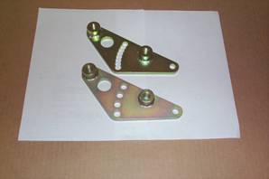
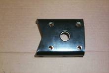
Also, in the rear suspension kit, we have provided British Automotive’s latest designed upper adjustable rear telescopic shock absorber mounting bracket set. Similar to its predecessors, this latest bracket design gives the installer a multitude of shock absorber installed height mounting positions. However, in image P0003584 below, you will see that we have significantly increased these mounting hole options. Left hand is shown.
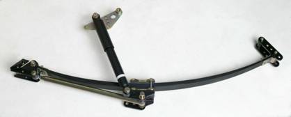
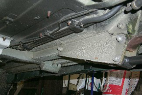
In image MGB-Suspension-7_07 below, you will notice that we utilize the lower front shock absorber mounting position, which is common on most conversion kits.
For your reference, In P0003584 above, A is the forward mounting boss (towards front of vehicle) and B is the rear-mounting boss (towards rear of vehicle). The holes are numbered from bottom to top, these adjustments are AB1 (Initial) AB2, AB3, AB4, AB5, AB6, AB7, AB8 (A adjusts in increments of approximately 1/8”) and (B adjusts in increments of approximately 1/2”). If you are working with the B mounting boss, the shock absorber installation angle will be significantly reduced; however, the efficiency will be increased. In which case, be sure to check and rectify any interference problems between the shock body and the right hand rear wheel cylinder brake line. Simple bending of this line is all that should be necessary.
In image MGB-Suspension-7_07 above you will notice a white strip on the lower portion of the shock absorber body. This strip indicates the shocks compressed position i.e. “bottomed- out”. Before installing your shocks, you will be required to scribe a similar mark in the same position around the perithary of the lower shock body. Fully compress the shock assembly and scribe this line. Do not compress shock absorber more than once.
Continuing: Because all mounting hardware is supplied in grade 8 (zinc plated), there may be issues with thread free-run. Before starting your installation, all mating nuts and bolts, excepting locknuts, should be lightly oiled and free-run with their mated part. Before installation, locknuts and there mated male thread should be lightly oiled also.
Using the appropriate MGB workshop manual, proceed and remove all rear suspension components that are going to be replaced.
NOTE: In the following installation instructions, it is assumed that the composite springs have already been installed. Therefore, some of the following instructions are based on this. Also, you may wish to carry out instruction #1 below during the composite spring installation procedure instead. Instructions are for one side, follow up with the opposite side.
- Using AB1 mounting hole, install new upper mounting bracket. There is no need to install the lockwashers at this stage, simply hand tighten nuts.
- Measure the distance between the rear axle bump stop pedestals and the progressive bump stop rubbers. This distance represents the amount of suspension travel available under "bump" conditions. I consider 2-1/2” to be the minimum allowable. Remember that the rear ride height has a direct relationship with this measurement.
- Temporarily install the shock absorber.
Using mounting boss A will result in an installed angle of between 20 and 25 degrees. Using mounting boss B will result in an installed angle of between 5 and 8 degrees.
NOTE: There is no need to install lower hardware 1/2” SAE nylok nut until the final position of the shock is known. However, before final installation, the shock absorber gases should be neutralized by fully compressing the shock and letting the shock return to its extended position. Repeat this at least 4 times.
Using British Automotive's specifically manufactured KYB gas charged shock absorber units; we now refer you to the following:
| PART (VBPBA1) | DIMENSIONS |
| Compressed Length | 10.0" |
| Extended Length | 16.0" |
| Working Length | 6.0" |
| Ideal "Bump" Travel | 3.0" * |
| Ideal "Rebound" Travel | 3.0" |
* Because the shock absorbers contain no internal bump stop, we have included 1/2" compression of the bump stop within this amount, thereby, preventing damage to the shock absorber from "bottoming out".
We have taken the same approach as in the MGBRV8 whereby, there are no axle check straps fitted for controlling axle drop. Instead, the actual Extended/ Length dimension of the shock absorber limit this movement. However, we leave these check straps in position, but disconnected at the rear axle-mounting pin. This allows the check straps to be connected whenever the shocks are disconnected and the rear axle has to be held suspended for any other mechanical work.
With 8 hole adjustments available, along with 2 (A&B) shock absorber mounting bosses, you should be able to install your shock absorber correctly. However, a final check should be made by measuring the distance between the scibed line on the lower shock body and the upper outer sleeve to be sure you have sufficient travel.
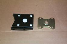
You will notice that the lower shock absorber mounting bracket “U” bolt holes have been CNC elongated to accept both the banjo axle and the tube axle “U” bolts. Since, these original holes in the bracket were subject to distortion in the mandrel bending process; some holes may look more professionally CNC machined than others may. To set up the CNC machine for each individual hole elongating process would have been impractical and extremely costly. You are probably wondering why we did this, well cost mainly. You see, instead of providing two different types of lower shock mounting brackets for the banjo axle and the tube axle, we decided that only one bracket was really necessary. This logic was born by observing exactly how the bracket was held and located to the rear axle tubing. With the help of the images below this should be easy to understand.
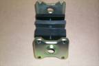
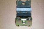
In image (P0003542) we see a bracket used only for the tube axle assembly modified to accept the narrower banjo axle type “U” bolts, along side with a tube axle “U” bolt guide plate. Now, viewed from below, (P0003544) this “U” bolt guide plate locates inside the lower shock-mounting bracket, by way of the center boss on the guide plate. In turn, this “U” bolt guide plate would locate over the spring seating pad which, in turn, locates over the spring center pin. So, all we need to do is to tighten the “U” bolts sufficiently to keep the whole assembly in place.
Of course, from the above, it is easy to understand how this type of method works when using this bracket on the banjo axle along with the use of banjo axle “U” bolt guide plates.
 |
 |
| P0003542 | P0003544 |
We have supplied you with 8 SAE washers and nuts for initial assembly only. When you are satisfied that you will not have to remove the lower shock absorber bracket again for any purpose, such as lowering the rear suspension by way of lowering blocks, use the additional 8 serrated flange type locknuts. Apply oil to the serrated flange face as well as the threads. NOTE: This style of locknut is reusable.
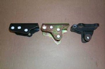
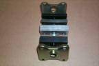
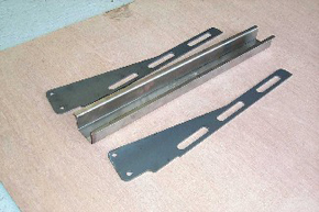
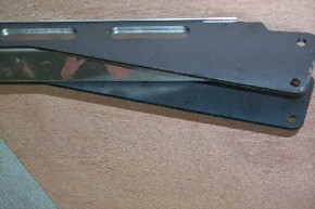
Some MGB customers may receive the zinc plated deeper brackets (center) as shown in image P0003364 These brackets were designed for use with both the OEM steel leaf spring, as well as the composite monoleaf road spring. You will notice that we have engraved a line duplicating the outline of the front bracket. If ground clearance issues arise with this deeper bracket they can be modified by way of laser or water jet cutting. Please do not ask us to be responsible for this procedure.
Please take note that the composite spring set is pre-assembled as would be fitted to your car under normal circumstances. The lower black Delrin spacer is designed to bring the assembly back to the approximate thickness of the OEM steel spring.
Your composite spring set has been designed to lower the rear of your vehicle by approximately 1”. However, since allowable spring rates are higher with composite materials, this may, or may not, result in the lower ride height which, you may be looking for. To this end, we have fitted the composite spring assemblies with additional 1/2” spacer blocks. This combination is designed to accommodate the OEM length “U” bolts. Your actual “U” bolt length will dictate any further lowering.
Should you wish to lower your rear suspension further, you alternative is to use Moss Motors lowering kits, part number 268-165 (Banjo Axle) or 268-140 (Tube Axle). We no longer supply longer “U” bolts.
In image P0003590 below you will see the 1” aluminum-lowering block as found in the Moss Motors lowering block kits. This aluminum block will sit directly on top of the composite spring blade. Our supplied spare nylatron spring seating pad would then fit on top of the aluminum block. Both these items will require Prothane lube. The “U” bolts supplied in the Moss Motors lowering block kits are 1” longer than the OEM type.
| 1/2" LOWER | 1" LOWER | 1-1/2" LOWER |
 |
 |
 |
| P0003588 | P0003590 | P0003591 |
NOTE: “U” bolt guide plates are shown for reference only.
So, your composite spring set will be assembled as shown in image P0003588 without the “U” bolt guide plates. If you do not require the 1/2” spacer block, it can be removed along with the upper nylatron spring seating pad. Do not try and separate these two items from each other as they are pressed together. We have supplied an additional nylatron spring seating pad, which should be fitted instead. Clean off composite spring blade and apply Prothane Teflon lube to this new pad.
If you are going to use the Moss Motors lowering kit and the supplied 1/2” spacer block, then assemble as in image P0003591.
If you are going to use the Moss Motors lowering kit only, disgard the supplied 1/2” spacer block along with the upper nylatron seating pad. Using the new nylatron seating, assemble as shown in image P0003590.
Please remember that lowering your rear suspension ride height after you have initially installed your shock absorbers will require that the installation procedure be undertaken again.
PLEASE NOTE: Unless changes to the rear suspension ride height are contemplated, the lower black Delrin spacer and the 1/2”spacer block with the upper nylatron spring seating pad have been pre-lubed and should not be removed. Also, it is extremely important that both of these items be firmly seated within their respective upper and lower “U” bolt guide plates.
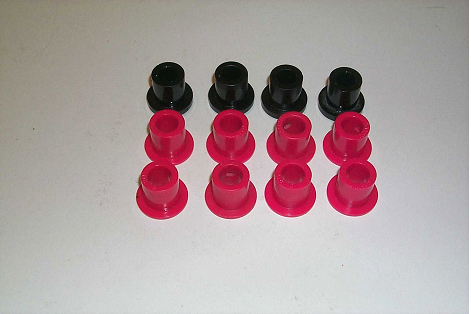
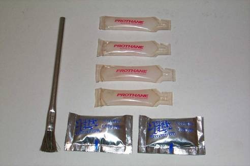
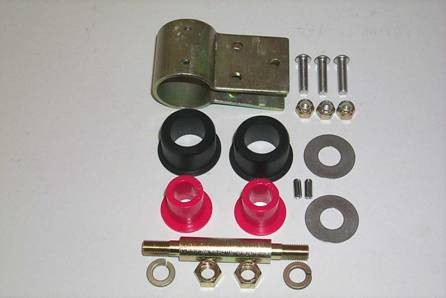
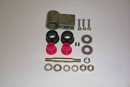
In the future, it may be necessary to replace the composite spring front and rear mounting hardware. To this end, we have supplied you with the following replacement bushings as shown in images P0002276 and P0002790 below.
8 - Replacement polyurethane spring mounting bushings (red)
4 - Replacement polyurethane upper shackle bushings (black
2 - SuperFlex lubricant packets
4 - Prothane teflon lube packets
1 - Applicator brush
 |
 |
| P0002776 | P0002790 |
Use the SuperFlex lube for all replacement red and black polyurethane bushings. Spring “drop-down” required for both of these operations.
Use Prothane lube on both upper and lower spring seating pads.
The large black Delrin bushings, as seen in P0002784 and P0002806 below, support the red polyurethane bushings, are now considered an integral part of the composite spring blade and therefore, not replaceable.
In the case of the front spring mounting assembly, it is extremely critical that installation instructions are carried out correctly, which among other things include deburring and smoothing the inner surfaces of the front spring mount body abutments, along with the rear upper shackle polyurethane bushing mounting holes.
| Front Mounting | Rear Mounting |
 |
 |
| (P0002784) | (P0002806) |
From all of the above text, it should be now easier to understand how rear axle lateral movement can further exaggerate front spring bushing wear. Please, as indicated earlier, I strongly urge you to install a panhard rod kit.
The following instructions are meant as supplemental instructions to those found in various MGB service manuals covering road spring removal and refitting.
- Proceed as outlined in MGB workshop manual.
- Remove front spring hardware from the spring mounting eye.
- Apply “Super Flex” lubricant to the outer faces of the red polyurethane insert bushings, both sides of the stainless steel thrust washers and the mounting pin.
- Making sure that the stainless steel thrust washers are not displaced from over the insert tube, fit the composite spring to the body mount abutment, insert mounting pin. Temporarily install 7/16” SAE plain washers and nuts.
- Remove rear spring shackle hardware from the spring mounting eye. However, DO NOT remove the lower 0.565” shackle pin. NOTE: Be sure to take note of how the shackle links are assembled.
- Insert upper shackle pin black polyurethane bushings “dry” into body mounting holes.
- Apply “Super Flex” lubricant to the inside surface and outside face of these bushings, as well as the 0.500” upper shackle pin.
- Insert pin with a twisting motion.
- Apply “Super Flex” lubricant to the face of the inner red polyurethane bushing, as well as both sides of 1 stainless steel thrust washer. This thrust washer locates over the unthreaded portion of the lower shackle 0.565” pin.
- Lift up spring assembly and engage the inner shackle link (easier to work with the inside first) with both the upper and lower shackle pins. Temporarily install 3/8” SAE nuts.
- Once again, apply “Super Flex” lubricant to the face of the outer red polyurethane bushing, as well as the remaining stainless steel washer.
- Locate stainless steel washer as in instruction #5 above, then engage the remaining shackle link. Temporarily install 3/8” SAE nuts.
- Double check that both stainless steel washers are correctly located then undo one 3/8” SAE nut at a time and install lockwashers. Do not overtighten.
- Install new TCA lower mounting plates, along with your Bump stop pedestals, “U” bolts, “U” bolt guide plates and, if necessary (as discussed previously within this technical article), British Automotive’s 1/2” spacer or Moss Motors 1” aluminum spacer block.
- Secure lower mounting plates with 3/8” plain washers and 3/8” SAE nuts.
NOTE: Upon final assembly, the above nuts should be substituted with the 3/8” SAE locknuts and tightened to 10.0 lbs/ft.
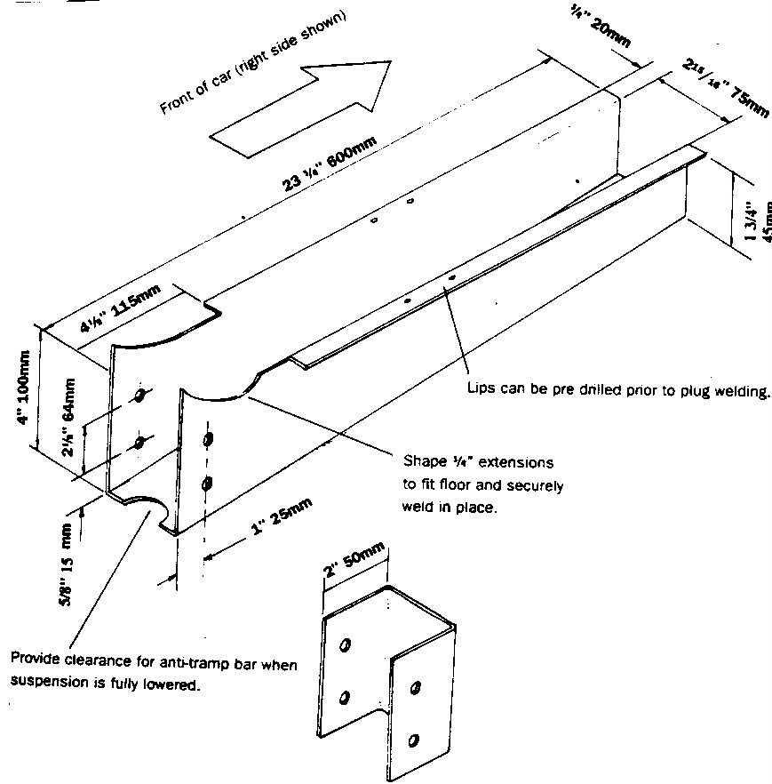
TCA FRONT MOUNTING BRACKET HARDWARE
(CHROME & RUBBER BUMPER MODELS)First, remove front spring mounting pin hardware (7/16” SAE plain washers and nuts).
NOTE: Please read the following before continuing.
Remove any interior sound deadening material that will interfere with the flush floorpan contact of the interior mounting hardware.
It is also essential that the underside of the TCA mounting flange brackets have metal to metal contact with the floor pan. Clean any material from the body in these areas. A light coat of black paint will prevent rusting.
NOTE: Depending upon your physical size, it may be easier to remove both passengers and driver’s seats.
TCA front mounting bracket to floorpan hole alignment is essential. Accurate marking and drilling of these mounting holes is required. However, having said that, I recommend having an appropriate sized round file on hand.
On the rubber bumper model TCA front mounting brackets, we have attached a basic floor strengthener “U” bracket. Before removing this bracket, note the position of the mounting hardware securing this bracket to the TCA mounting brackets.
- Place the black powder coated TCA brackets over the threaded pin, finger secure 7/16” hardware.
- Remove brackets.
- Pilot drill (1/8”) these 3 locations.
- From inside the vehicle, locate these pilot holes and drill to 21/64” (2) and 17/64” (1) Note the size of the appropriate holes required.
- From the underneath of vehicle, deburr these holes.
- Refit brackets and finger secure 7/16” hardware.
- Install and finger tighten the complete interior mounting bracket hardware. Be sure to install the correct amount of 1/4” flat spacer washers between the outer TCA mounting brackets and the floorpan. We have provided more than an adequate amount of these washers.
NOTE: We have supplied a basic TCA front mounting strengthener kit for your vehicle. You may, or may not wish to install this kit. Customer feedback indicates that in many cases it is not necessary.
The degree of difficulty in installing the above kit is moderately high. However, with patience and carefull drilling of the mounting holes, especially the lateral holes that run parallel with the body, you will be more than happy with the end result.
Having stated the above, should you be putting a great deal of horsepower down at the rear wheels, you may wish to check out images P0002647, P0002649, and P0002651 at the end of this technical article.
- Scribe the elongated holes on the side of the TCA mounting bracket onto the front spring mounting body abutment.
- Remove the inner and outer TCA mounting brackets.
- Using a small chuck electric pistol drill, or a pistol air drill, or a right angle electric drill, drill 1/8” pilot holes in the center of these scribed elongations, followed by a 21/64” drill bit.
- Refit the TCA mounting brackets again and finger tighten the 7/16” hardware along with all interior hardware, except the 1/4” bolt.
- Place the inner floor pan strengthener plate into position. Mark the 21/64” hole periphery on to the floor pan. Be sure to remove any sound deadening material so as to allow for flush mounting of this plate.
- Drill 1/8” pilot hole in marked floor pan, followed by 21/64” drill size.
- Deburr drilled holes on both sides of the floor pan.
- To prevent floor pan from rusting, spray paint these areas.
- Secure the inner floor pan strengthener plate with 5/16” hardware.
- Position “U” bracket and insert additional provided hardware (5/16” SAE X ¾”bolts, flat washers & nuts, with bolts inserted from inside to outside).
- Using flat washers only, finger tighten hardware.
- Mark the 4 hole locations onto the floor pan.
- Drill 1/8” pilot holes thru the floor pan but not completely thru the inner strengthener plate.
- Mark the TCA outer mounting ¼” hole location on to the same plate.
- Remove inner strengthener plate and pilot drill 1/8” followed by 21/64” (4) holes, along with 1/8” pilot hole (1) followed by 17/64” hole.
- Remove “U” bracket hardware and “U” bracket.
- From inside the vehicle, drill out the 1/8” pilot holes (4) to 21/64”.
- Deburr both sides of these holes.
- Place the “U” bracket and inner strengthener plate in position.
- Screw in interior 5/16” hardware (4) thru the plate, and finger tighten.
- Screw in interior 1/4” hardware (1) thru the plate, and finger tighten.
- Using the long 5/16” bolt, spacer tube, spacer washers (as necessary) refit “U” bracket and all hardware. Finger tighten hardware.
- With all lockwashers and flat washers in position, tighten all hardware.
- SuperFlex lube the rear TCA tube mounting bushings inner diameter, end faces and the aluminum spacer tube. Insert tube into bushings.
- Assemble TCA tube to the TCA rear-mounting bracket.
- Adjust TCA front heim joint and install hardware.
- Tighten all hardware.
Continuing from previous instruction #11. (before rubber bumper installation instructions)...
NOTE: The following instructions should be carried out under the same conditions and at the same time as the shock absorber installation.
| OEM MG RV8 | MGV8 TCA FRONT MOUNT KIT (CLIVE WHEATLY 011 44 1746 710810) |
|
 |
 |
 |
| P0002647 | P0002649 | P0002651 |
You will notice that the OEM MG RV8 set up incorporates a box type tube extension in the design of the front spring mounting and the TCA front mounting area. It is not practical to utilize this set up in conjunction with the regular MGB chrome bumper and rubber bumper models.
A further TCA front mounting modification that canbe found in a SPEED PRO SERIES publication titled “How to improve MGB, MGC & MGB V8”, is shown below. The Moss Motors part number for this publication is 213-170.